| Enable | D (data in) |
Q (data out) |
|---|---|---|
| 1 | 0 | 0 |
| 1 | 1 | 1 |
| 0 | X | Q |
Some background topics.
This is not now (currently?) ‘mainstream’ design and the
page can be omitted.
However transparent latches, at least, still appear in parts libraries
and do have occasional uses.
Two state-holding elements (at least) should be familiar by now:
The former is clearly a synchronous component. Historically, RAM was typically asynchronous (acting as a combinatorial component) but most modern RAM blocks have a synchronous interface. Thus writing to a RAM requires an active clock edge (like a DFF) whilst read data appears as the result of ‘clocking in’ the address†.
†Note that this means a RAM has a one cycle read delay.
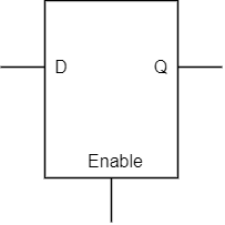
The transparent latch (or just “latch”) is an asynchronous storage element. Like a D-type flip-flop it has a data input and output but instead of an edge-triggered clock it has a combinatorial enable input. Its characteristics are:
| Enable | D (data in) |
Q (data out) |
|---|---|---|
| 1 | 0 | 0 |
| 1 | 1 | 1 |
| 0 | X | Q |
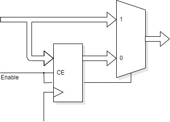
It is possible to make something with quite a similar function to a latch from a D-type, as shown. (It is not quite identical.) This can be useful when a data element might be ‘forwarded’ to a subsequent stage within (timing permitting) the cycle in which it arrives. However if it cannot be accepted immediately the register will capture it for future and be held until consumed (where the controller removes ‘Enable’).
always @ (posedge clk)
if (Enable) register <= data_in;
assign data_out = Enable ? data_in : register;
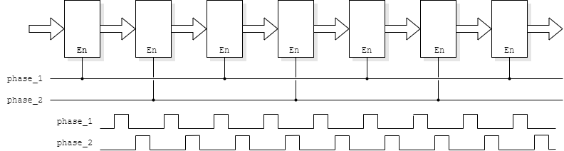
Rather than use master/slave flip-flops we can use smaller, transparent latches. These are enabled by alternating, non-overlapping clocks.
This is mostly of historic interest. If you're interested in early
microprocessors you may come across this.
E.g. Intel
8080: see pins 22 & 15. Area mattered: note
the technology node where modern devices have more than a million
(1000×1000) times the transistor density.
Return (or forward!) to clock distribution.