The normal clock source for digital logic is a crystal-controlled
oscillator. These use vibrations in a carefully machined (piezo
electric, usually quartz) crystal to stabilise an electrical
oscillator circuit. Without any special care a frequency within about
50ppm† is usual. If it matters, much greater
stability is, of course, achievable as is demonstrated by
‘quartz clocks’.
- No two independent oscillators will run at exactly the
same frequency.
- If a constant phase relationship is required a single oscillator must
be used.
†Equivalent to about 4 s error per day.
Frequency examples
- Digital logic is operated at frequencies of several GHz
- For ASIC design, typically think 100s MHz
- Humans tend to prefer simple numbers such as 20 MHz
- A ‘serial line’ (old fashioned now) has standard baud
rates of 9600, 19200, 38400, 115200 … Hence multiples of such
frequencies are not uncommon.
- Example: 18.432 MHz = 30 × 16 × 38400 =10 × 16 × 115200
- USB uses bit rates of 12 Mb/s (USB 1), 480 Mb/s (USB 2)
- In I/O applications there is commonly some tolerance.
- E.g. RS232 ± a few percent
- USB 480.00 Mbit/s ±500 ppm,
12.000 Mbit/s ±2500 ppm
Frequency and phase
It's only meaningful to talk about frequency with respect to
repetitive signals.
The frequency of a clock is the reciprocal of its period.
f = 1⁄T

With two or more signals there may be a phase relationship.
Same frequency, different phase.

Harmonic frequencies (phase relationship is fixed)

Non-harmonic frequencies: phase relationship drifts

It is increasingly common to have blocks running at different
frequencies. This is sometimes referred to as GALS
Globally Asynchronous Locally Synchronous.
Or possibly the same frequency, but ‘uncertain’ phase.
- Sometimes just reduce (divide) master clock
- Sometimes have separate clocks.
Clocking, frequency and power
The majority of the power dissipation in CMOS logic is dynamic,
i.e. it occurs when gates/wires switch. Thus – when
executing – the power dissipation is roughly proportional to the
clock frequency. Reducing the frequency saves power (dissipates less
heat).
The clock network is a significant source of power dissipation. The
power used is (effectively) proportional to clock frequency. Thus it
makes no sense to clock a circuit faster than is necessary. Clock
gating may be introduced to stop clocks when a block is unused
– but this should be done with caution!
Clock Gating
If part of a device is not in use, its clock may be stopped
(‘gated’). This is more power-economic than simply
‘disabling’ the registers because it prevents (parts of)
the clock tree from switching.
However there are several concomitant hazards and it's easy to
introduce unpleasant clock skew or even glitches if care
is not exercised. Don't do this ‘by hand’ until you've
lots of experience!
Implementing clock gating is best left to the tools (if
available). Note that adding gating may compromise peak performance
so is not always desirable.
Changing frequency
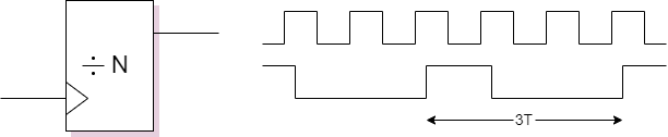 Reducing frequency – by an integer factor – is easy.
- Note that dividing by an odd number will result
in an uneven duty-cycle
- This may or may not matter to you
- The output clock will have a fixed (unknown) phase relationship
with the input.
Increasing frequency is more difficult: use a Phase-Locked Loop (PLL)
These include some mixed-signal (analogue) components …
… but can usually be bought-in from a specialist designer.
Why bother?
- It is difficult to carry UHF signals across a PCB; great care with
tracking is required.
- Switching signals dissipates power. The more you switch, the more
it costs.
- Switching signals transmits Radio Frequency Interference (RFI).
(Where do you think the power goes?)
This is a Bad Thing, and may be illegal.
- Generating stable clocks at UHF directly is impractical.
A typical clock source will be a crystal controlled oscillator. These
are cheap and quite precise. Frequencies of the order 1-100 MHz
50ppm are readily available. However modern computers are typically
clocked much faster.
So, the usual ploy is to supply a stable frequency (say 20 MHz)
to the chip and then multiply this on board to the desired clock rate.
A bonus from this strategy is that the clock multiplier is digital and
can be controlled (e.g. in software) allowing a trade-off between
performance and power consumption.
Another strategy is to reduce the clock rate – to reduce power
dissipation – if the chip is becoming too hot.
Phase-Locked Loops (PLLs)
A PLL is a machine
capable of matching the frequency of an input signal.
Everyday example
Consider a television set. It must display images at the same rate as
they are broadcast. Thus it needs synchronisation information so that
it can adjust its internal timing to match the transmitter. Of
course, in modern sets at these slow speeds this can be done digitally
by varying the number of ‘local’ clock cycles in each
line, frame, etc. slightly.
You can see this in the lab. (phase 3) with the
‘sync.’ signals running to(wards) the monitor.
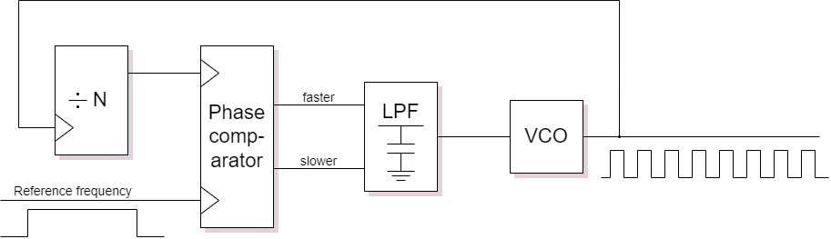
Clock multiplication
The figure above shows a clock multiplier which works by matching a
division of an output clock to an input reference.

LPF – Low Pass Filter
A typical phase comparator produces pulses on its outputs which
indicate which input edge came first. These need integrating
(smoothing) to produce a voltage which is (approximately) stable over
many clock periods.
VCO – Voltage Controlled Oscillator
An oscillator which runs ‘naturally’ in a certain range of
frequencies which is ‘tuned’ by an analogue input voltage.
Because a PLL circuit is controlled by feedback its output frequency
will vary slightly around the nominal frequency. This contributes
to clock jitter – the perceived variation in clock
frequency. Jitter is a Bad Thing because the logic must always
evaluate within the shortest clock period (not the
average) and the more variation there is the shorter this minimum time
will be.
Definitions to remember
- Skew: the difference in arrival time of a signal at different
destinations.
- Clock jitter: the variation of a clock frequency around its
specified value.
Back to time stealing.
Forwards to other timing stuff.
Up to Clocking.